Hello,
I decided to create a small “blog” page dedicated to my CNC machine building process.
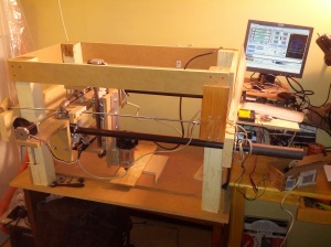
Building a CNC machine is FUN. The result.. Well, my idea was to build it as cheap as possible, so .. Yeah it looks cheap and crappy.
I was inspired by Patrick’s idea to build CNC using black pipes and flanges.
http://buildyourcnc.com/s1m2.aspx
I thought the idea is great and I can build a machine like that in a weekend! Oh well 🙂 maybe in two weekends… That was 6 months ago.
I used the idea, came up with basic design in my head, gathered all the junk i had laying around my garage, ordered a bunch of parts (motors, pipes, bolts, etc, etc) and started putting it all together. The result would probably be much better if I spent time to build full 3D model in CAD first, but I was too impatient.
So, I think my creation can be served as a great “How not to build CNC” example.
Here are a few grieves I had with this design:
- The first disappointment was when I realized the pipes have “taped” threads. That’s a “conical” thread that gets tighter with every spin. Taped thread doesn’t allow to set the pipe in a precise position. Also it doesn’t hold pipe well – it’s either too tight or too flexible.
- When I made a frame using only pipes and flanges it had no rigidity whatsoever. I ended up adding MDF boards everywhere, pretty much negating the whole idea of making all-metal frame.
- The bolts that compress two flanges on the pipe are only good for compression, not for rigidity. They allow the upper flange to move independently from the bottom one skewing everything.. Somehow I didn’t realize it until late in the project. Again I had to add MDF supports.
- My idea for Z-axis was not well thought, again had to add MDF inserts, because the bottom flange is not really holding anything.
- I couldn’t come up with any good place to put the X-axis threaded rod. Initially I wanted to put it in the middle of Y axis, but my Z axis ended up to be so tall that I couldn’t do it. Now I have it on one side of the machine only, which is pretty bad. I can probably improve the situation using another motor and having two rods moving in sync, but my board only allows for 3 motors, so it will be a future upgrade.
- My router “support board” on the Z axis is too long. It’s flexing like crazy. So far I added two aluminum angles to stiff it a little bit, but it’s still way too flexible. I think I need to make it shorter and use something like steel c-channel instead of MDF.
- For some weird reason I used 4×4 studs to keep the frame. I had them laying around, so I thought they would be fast way to build a strong frame.. Well, it’s strong, but they take a lot of precious space. MDF sheets would be probably strong enough and leave a few more inches of usable space.
Now the good things:
It actually works! I was able to cut a few things.. Not so bad for a first try, hopefully I can improve the quality with some tinkering.
I was really afraid of pipe sagging. But so far i didn’t notice any, probably because overall build quality is so bad that there are much worse problems 🙂
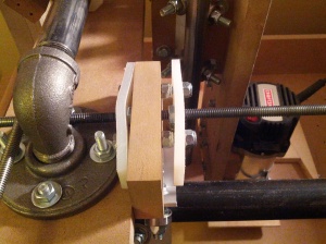
I didn’t want to buy ACME rods and expensive anti-backlash nuts for the first build. So I made simple anti-backlash nuts using two pieces of plastic cutting board and two steel nuts. I really like this design. It looks ugly, but works pretty well. I can run the machine at 20 ipm, which is about what I expected from cheap rods.
Connecting motors was a snap, much easier than I thought.
Here are a few pictures (please excuse the quality – used a cellphone in a darkness of my garage):
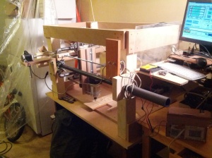
It’s mounted on 4×4 studs and 2×6 boards are supporting the pipes:
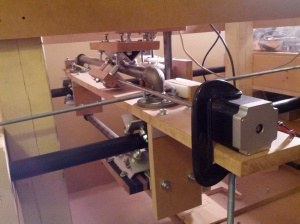
Gantry is moving on bearings along the pipes:
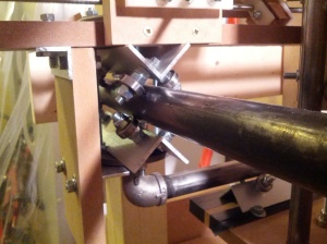
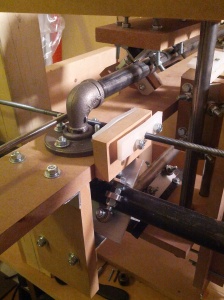
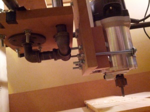
Here’s Y axis, using 3/4″ pipes and flanges:
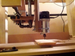
Z axis is also using 3/4″ pipes and flanges:
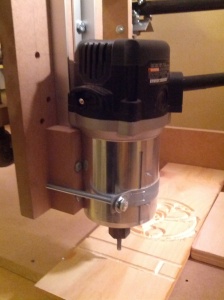
Here’s my router:
Simple anti-backlash nut:
